
Electrical Architecture Finalized
After a few months of design, we finalized the electrical system architecture of the electric Opel GT. Our design philosophy was to create small, simple modules that all interface over a shared CAN bus and tie the Motor Controller, BMS, and charger together. The diagram shows the architecture including the power sources for the modules. Signals are shown with thin lines and power connections are shown in bold. This diagram is abbreviated, but shows the significant details for the turn-on and turn-off of the vehicle. Six of the modules in the car are being designed in house, while three others are commercial products.
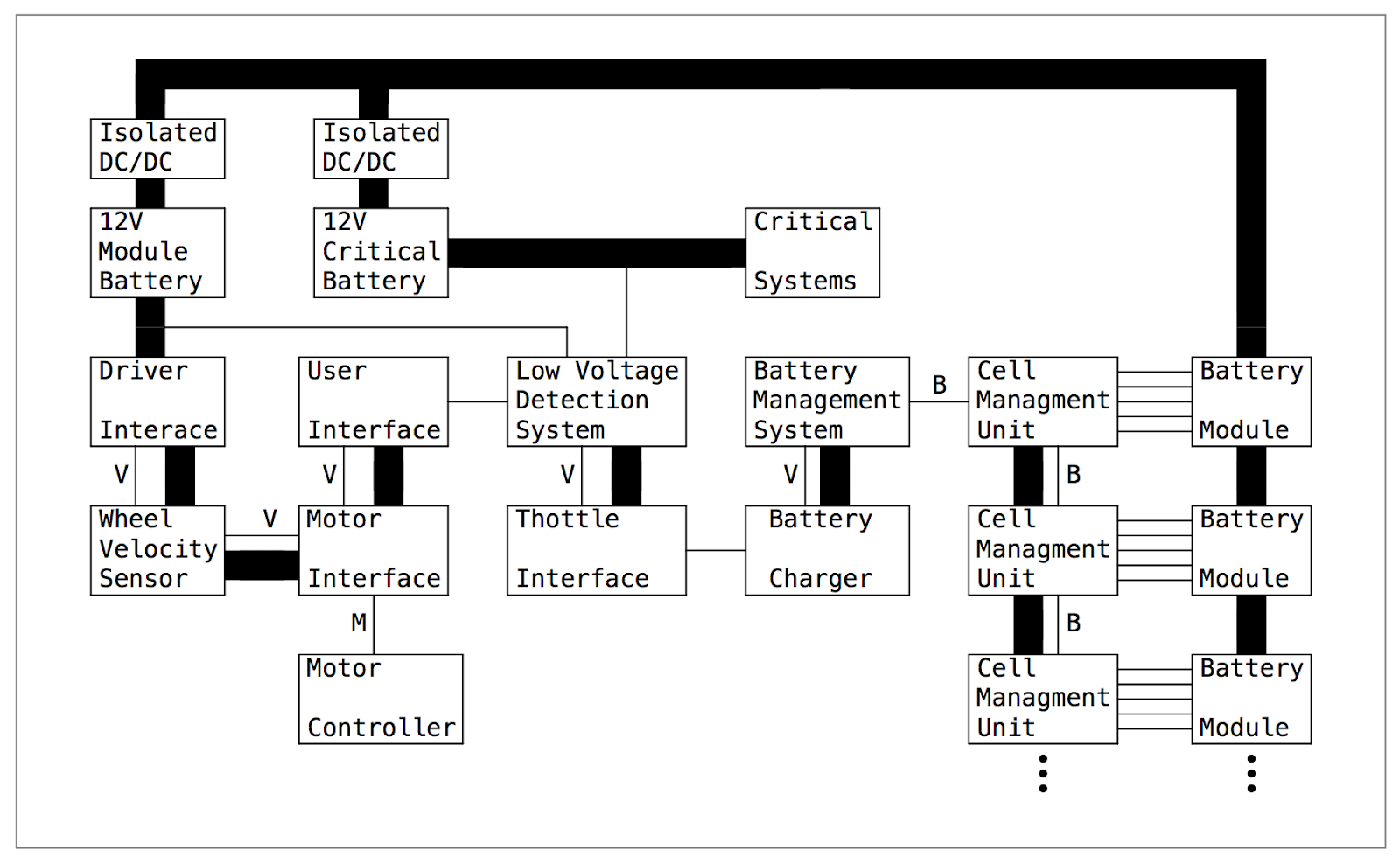
In-House Modules:
- Driver Interface: Acts as interface between user controls and their associated peripherals (ignition, lights, drive mode, etc). Controls the state of the vehicle.
- Throttle Interface: Reports throttle and brake pedal positions and ensures accurate readings with redundant measurements.
- User Interface: Responsible for reporting status of the vehicle to the user through gauges, indicator lights, and displays. Also responsible for logging vehicle state.
- Wheel Velocity Sensor: Reads vehicle velocity from hub sensors and broadcasts to the vehicle.
- Motor Interfaces: Acts as the interface between our modules’ CAN bus and the sevcon CANOpen bus. Also generates control signals for motor controller.
- Low Voltage Detection System: Monitors low voltage power buses and backup power sources
Off the Shelf Modules:
- Tritium IQ Battery Management System
- Sevcon Gen4 Size 10 Motor Controller
- Brusa NLG513 Charger
All of the modules will reside in small aluminum extruded enclosures. All the PCB’s are designed from a common template to keep input/output connectors the same, allowing us to design only one faceplate. Each module will have one 8-pin CAN/Power connecter, one 23-pin auxiliary connector, one 6-pin programming header, and breakout for up to 8 status LEDs. An NXP LPC11C14 microcontroller is the heart of each module, powered off a shared 12V power bus.
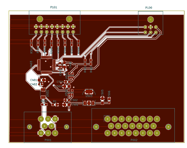
A prototype of the Wheel Velocity Sensor module was completed today. While the 9 pin can connector was not available from digikey, all other components have been assembled and tested.
We are excited to have our first module complete and to see through the completion of several more over the next few weeks. We hope to have our custom designed hardware for all of the modules in hand within the next two months, working in a prototype state on our testbench shortly after.


No comments:
Post a Comment