Sunday, January 19, 2020

Milan / elEVen Teardown

'Twas a bittersweet morning, as several EVT members and alum gathered to bid farewell to the Milan / elEVen project. Having had the car sitting in a covered storage facility since June of 2011, the car was becoming more of a liability than an asset. Those who helped build it had long graduated and moved away, and it has been one of my personal goals to make sure the vehicle was properly recycled before I graduate for the third and last time (fingers crossed for 2021). The car had largely been forgotten as the chain-drive system that connected the Northrop Grumman electric motor to the former-rear differential turned front differential sought to shake the vehicle apart under moderate torque loads.

With planning taking a few weeks, Jack and I used a tow dolly to secure the front wheels and tow the vehicle out of the garage, through several gates, and back to the N51 garage where it was built.
Loaded, secured, and ready for a short tow. Note the layer of dust caked into the vehicle.

At N51, Jack grabbed an extra (or 5) sets of hands to help push the vehicle into the bay. The lifts are long gone, but there was an engine hoist, a few sets of jack stands, and a small floor jack to get the work done on Saturday morning. Much of my personal Friday night was spent scraping the MIT and sponsor decals off the vehicle. 8+ years of the parking garage dust and emissions had eroded and pock-marked much of the paint, but the paint below the decals was immaculate. Don't worry, only plastic instruments and a touch of heat were used to remove the vinyl decals.

Many of the decals removed along with the hood. Calling it a night a few hours of work and a Beantown burrito (one of our sponsors for the trike project).


Saturday morning started with more decal work, removing the 12V battery systems, and ensuring that the high voltage lines to the engine compartment were powerless. Jack and I were joined by Jarrod and two other talented friends. With their help, we were able to get the motor and controller pulled by 11.
Accessories box removed. 9:53 AM
Motor assembly out and clear of the vehicle. 11:00 AM. Note the chain drive on the viewer left, and the rear differential turned front differential lower right.
Meanwhile, during this process, three of us were set removing the 12 A123 battery modules that made up the 360V pack. We initially thought that they could not be salvaged, but it turned out that they were at 99% of their nominal voltage. I was quite impressed, and glad that we had salvaged the pack in lieu of letting the scrapyard inherit the liability of disassembling the pack.

Battery pack in rear trunk, start of disassembly 9:53 AM.
In regards to the pack, the blowers for high speed charging were removed easily, but the front cross member could not be safely removed without putting the seat down. Further, someone had cut the release mechanism for the seat years ago (for safety?), so it was removed piece-wise. Jarrod led the work in the rear, and we could not have done it without his guidance.

We were all set to roll it out and to the junkyard by 12:10, in time for their 1:00 pm close time, but they wanted to postpone to Monday, so we set it out to pasture until it's pickup. It did gain quite a bit of suspension height in the process though.

Out to pasture. PC: Jack
Looking forward, let us know if you have any ideas on what to do with the motor and battery pack combo. We're also very short handed though, so undertaking an entire vehicle, especially of the modern vintage, is impossible to do well. Are there any challenges or competitions we can set our sights on to rekindle the team?

Monday, October 31, 2016

Update from beginning of the year


For over a month now we have been engaged in training a new class of MIT EVT members on both the Meche and EE subteams. With a new year comes a new focus, as the Meches push to finalize the design for the entire front compartment and the EEs work toward generating a working test bench along with designing our battery management system (BMS) with the FSAE team.

As usual, we opened up the year with Rango lecturing to the new members about high level concepts.
Rango lecturing at first meeting

As time progressed, our new members became much more proficient in Solidworks as well as some fabrication techniques, with them being able to make progress toward generating a complete design of the front battery mounting structure, gain a better understanding of the volume available to us in the front section of the car with a point cloud, and beginning to use configurations in Solidworks in order to reduce clutter and make changing any cad easier. 

On the EE end, we had our usual meeting about work status and work goals. We currently have a few groups tackling some very big tasks: LV electrical system (think headlights), our custom dashboard for our electrical systems, customized LCD screen for more detailed information, and our new BMS project with MIT's FSAE! We also briefly went over the pros and cons of DC-DC regulators and linear regulators and how we use them in our power distribution network. 

Meche team meeting

We have also begun doing weekly exec, Meche, EE, and team meetings in order to get better organization as well as to help everyone remain informed as to how their tasks relate to the everyone else's tasks and plan out how they will attack their problem on Saturday.


Saturday, February 13, 2016

Battery Update: Front and Rear Pack Arrangement

 After a long week of CADding and designing, Joey managed to generate a design for the front and rear packs of our car thanks to input from the meeting of the minds we had last week. In total this pack will be 58s64p distributed between the front and rear of the car, giving us a roughly 72kWh pack! The team had an internal design review this past Saturday with Prof. Dan Frey to look over everything, see if any considerations were left out, and generate ideas about wiring and assembly of the packs.


Tuesday we had a design review with our battery providers Boston Power. The meeting went well, and they provided us with even more ideas to consider including crashworthiness, cooling, wiring, and weatherproofing. 


Saturday, February 6, 2016

This week in EVT EE

(note: this post was written by a new member without a sense of humor)

Preparations to command someone else's magical metal box to use electrons from large energy boxes to spin something.

IMG_20160130_151240.jpg
caption: magical metal box; alt-text: Sevcon motor coftroller
IMG_20160130_151952.jpg
{caption: Magical metal box's life support system; alt-text: 12-volt power supply}
IMG_20160130_151728.jpg
{caption: a smaller version of our large energy boxes; alt-text: The real ones are much nicer, I'm told}
IMG_20160203_203524.jpg
{caption: DC and smaller than what we are using, but it still spins right?; alt-text: The real motor is AC and much larger}
Some little metal strings go between our squirrel containment facilities and the giant metal box to allow the magical squirrel inhabitants to talk to each other.
IMG_20160130_151445.jpg
{caption: metal strings; alt-text: wires}
IMG_20160130_151537.jpg
{caption: squirrel containment facility; alt-text: our devboards at work}
The metal box really wants to talk to someone, but our squirrels were deemed too unimportant because they don't know the secret password.

To learn about the metal box, we needed to stare at lines formed by small squares on a glowing rectangle.
Once we decided that the lines failed to contain the information we needed, we pressed large buttons repeatable to create our own lines for another human to interpret.
That human, a person that works with the creators of the magical metal box, will give us the secret password that their squirrels require.


More clear explanation:
This week, we worked with the Sevcon Gen4Size10 motor controller.
It sits on a table with power supplies rather than the actual batteries for testing.
After working for a while to learn how to use CANopen, and reading through the documentation for the motor controller, we began trying to talk to it using our devboards.
We found that the motor controller is in master mode, and tries to send out a SYNC message to tell the other CANopen nodes to talk to it.
After trying to write values to the motor controller to change it's ID, disable the SYNC message, and switch it to slave mode, we found that it was always broadcasting an error message with each attempt.
The error message pointed us to another CANopen index to read, which informed us that we do not have a high enough access level.
In order to change the access level, a password must be provided to the Sevcon.
We have sent an email to a representative at Sevcon asking about the password.

MechE Battery Party!

MechE Updates

Our primary concern today was designing structures to hold and support our battery packs in the back of the Opel. By the afternoon, literally everyone on the MechE team was engrossed in this task. We were even honored to have Sir Nicholas Arango from the EE team come and help us generate ideas.
Being a team with a small car and big ambitions, one of our biggest design constraints in our Opel project is that we have 464 individual battery packs to distribute between what used to be the engine compartment and the space which used to house the back subframe and gas tank. Each group of cells has to be housed such that none of the cells are at risk of being ruptured in the case of a collision. At the same time, the front and back compartments each require a cooling system for these cells, and in addition to our subframe, motor, and transmission in the rear compartment, each compartment will eventually house one or more modules such as our motor controller or our battery controller. Our design constraints, therefore, are difficult to work with, and it took hours narrowing down what path we should take.

Alex helping lead discussion. Alex and Joey, who had done a great deal of work designing our battery supports in weeks past, proved invaluable.

Leave it to Rango to bring out the best in people.

After hours of work, first in small subteams and then as a whole, we were able to come up with a modular design for our supports which could be implemented universally across virtually any permutation of battery placement. We designated two teams—one to generate plausible battery placements with batteries oriented towards the back of the vehicle, another with cells toward the passenger side—to create a library of battery placements to choose from. This coming week, we will select the design that seems most feasible, stable, and space-conscious so we can start building the support frame itself.


A set of one of many sizes of battery module CADded by Joey
In addition to this, Jacob, Ryan, and Olivia worked with Jimmy from the EE team to decide how and where to mount potentiometers to the accelerator and brake pedals in the Opel, and Joey created comprehensive CAD of the structural members of the Opel frame.


Joey’s CAD of the structural components of the Opel frame


Thursday, January 28, 2016

EE Team Updates


Today the EE team converged once again to check in regarding what each of us were working on, if we were stuck on issues, and finally, discuss the very important (and safety critical) shutdown sequence of the car.

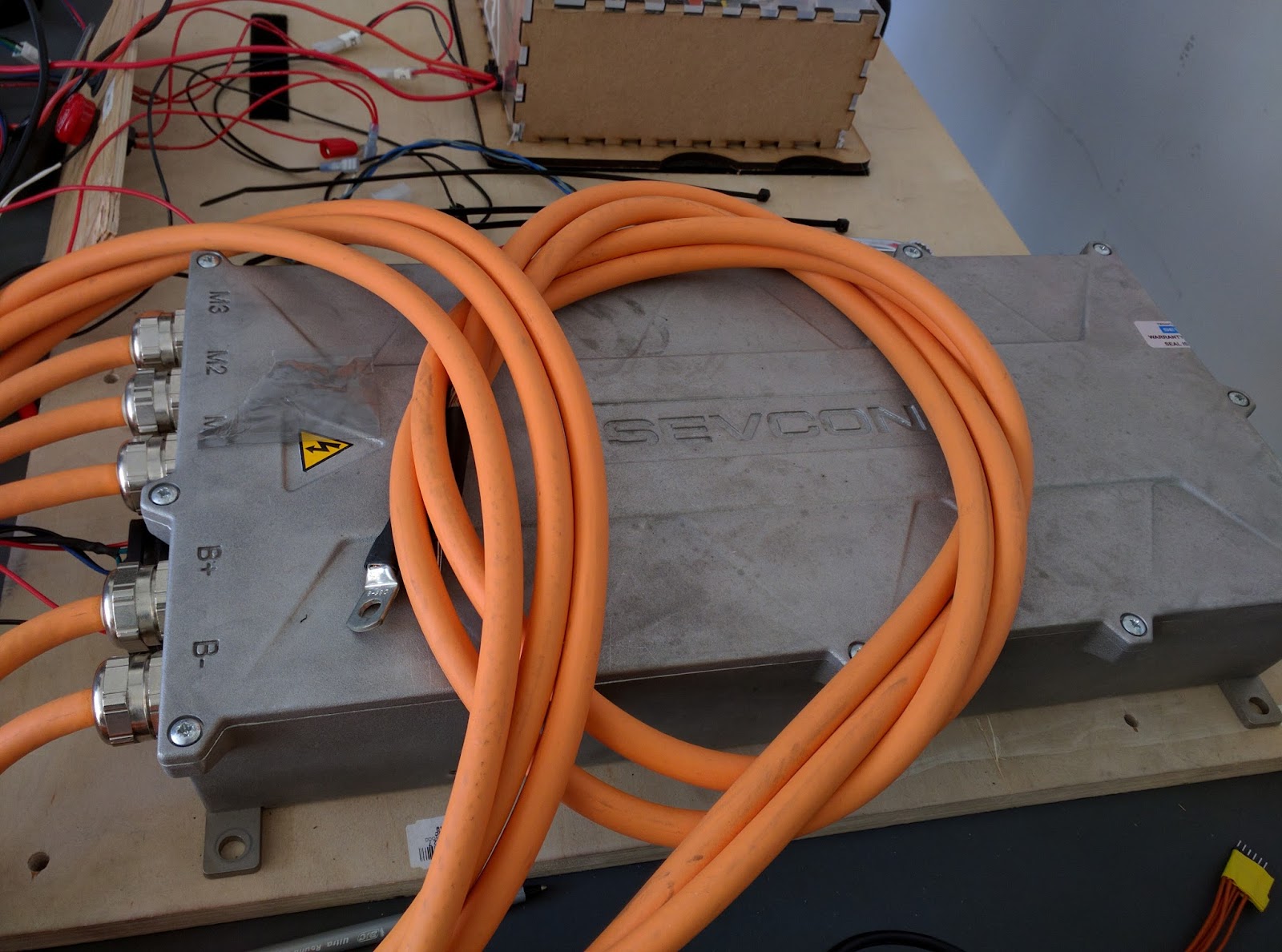
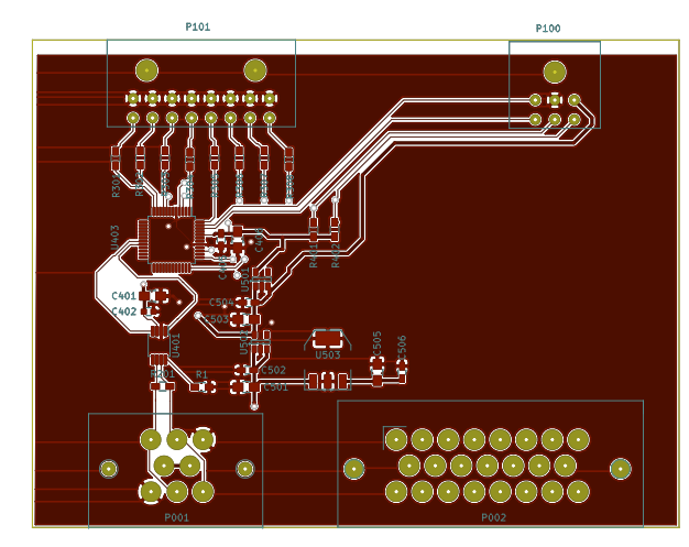
First, Rango discussed a sizing issue that was realized after our newly printed PCB was put into our lovely-looking, insulated PCB enclosure:

IMG_20160126_202156.jpg
The EE team apprised of a redesign: our first printed PCBs had not accounted for the size of the lips/flange of the adaptor connecting the PCB to peripherals, CAN bus, and power lines. As such, the cover to the insulating box surrounding the PCB does not lie flush to the PCB. Unhappiness.

We then went through in detail exactly what sequence of events needs to happen the moment the driver turns the key to “off” (assuming no critical errors initiating or during the shutdown sequence - we’ll handle that next Tuesday). In our discussion, we took into account safety checks, possible design improvements to our sequence, and the conditions necessary to safely turn off the vehicle.   The following is the Opel’s democratically-decided shutdown protocol:

shutdown-sequence_1.jpg
The team’s white board design of the checks and action sequence that the car’s driving state machine ought to undergo in order for the car to safely shutdown.

Our team checked in at the beginning of the meeting to discuss their current projects, their short-term goals, and the obstacles that they need to overcome.

Rebecca continued her work on the User Interface Module. Specifically, she is working on getting test examples on the SPI protocol up and running, and beginning to write the code for the User Interface.

Toby is continuing his work on the Power Distribution Module. He is going to add connectors to his computer and experiment with the gauges so that he knows he is able to communicate with them using I2C.

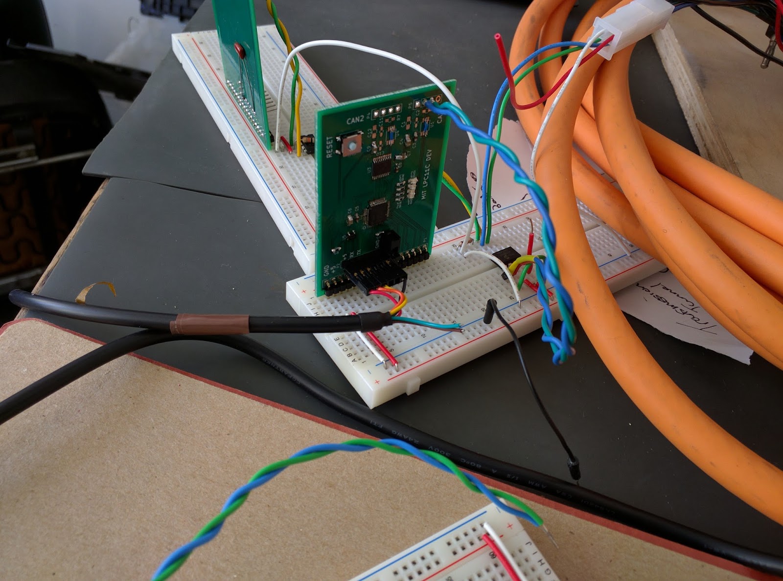
Jonathan located a handful of 2-twisted-wires that we will use to wire the CAN bus. He also started working on matching up pins in each module’s external peripheral/CAN bus connector.

Skanda/Bryson

The Skanda and Bryson duo are writing unit tests for the Driver Interface. Certain functions in their driver utility code currently do not have tests written for them, so they will continue to work on that in the near future and work on implementing the car initialization sequence.

Hugo - electric vacuum pump to buy; pricey, but had all the comments

Hugo was looking for more improved parts to use in our braking system. He found an electric vacuum pump that satisfies all of our requirements and that was more efficient than our previous pump. Even though the part is pricey, he felt that its functionality was worth the cost.

Jordan continued working on designing the circuits used to control the driver interface relays.

Helmuth managed to talk to the motor controller (!), getting a motor interface communication example using CANOpen up and running!

The team is busily working on finishing the OpelGT system modules!

Electrical Architecture Finalized


After a few months of design, we finalized the electrical system architecture of the electric Opel GT. Our design philosophy was to create small, simple modules that all interface over a shared CAN bus and tie the Motor Controller, BMS, and charger together. The diagram shows the architecture including the power sources for the modules. Signals are shown with thin lines and power connections are shown in bold. This diagram is abbreviated, but shows the significant details for the turn-on and turn-off of the vehicle. Six of the modules in the car are being designed in house, while three others are commercial products.


evt arch.png


In-House Modules:

  • Driver Interface: Acts as interface between user controls and their associated peripherals (ignition, lights, drive mode, etc). Controls the state of the vehicle.
  • Throttle Interface: Reports throttle and brake pedal positions and ensures accurate readings with redundant measurements.
  • User Interface: Responsible for reporting status of the vehicle to the user through gauges, indicator lights, and displays. Also responsible for logging vehicle state.
  • Wheel Velocity Sensor: Reads vehicle velocity from hub sensors and broadcasts to the vehicle.
  • Motor Interfaces: Acts as the interface between our modules’ CAN bus and the sevcon CANOpen bus. Also generates control signals for motor controller.
  • Low Voltage Detection System: Monitors low voltage power buses and backup power sources
Off the Shelf Modules:
  • Tritium IQ Battery Management System
  • Sevcon Gen4 Size 10 Motor Controller
  • Brusa NLG513 Charger


All of the modules will reside in small aluminum extruded enclosures. All the PCB’s are designed from a common template to keep input/output connectors the same, allowing us to design only one faceplate. Each module will have one 8-pin CAN/Power connecter, one 23-pin auxiliary connector, one 6-pin programming header, and breakout for up to 8 status LEDs. An NXP LPC11C14 microcontroller is the heart of each module, powered off a shared 12V power bus.


A prototype of the Wheel Velocity Sensor module was completed today. While the 9 pin can connector was not available from digikey, all other components have been assembled and tested.

We are excited to have our first module complete and to see through the completion of several more over the next few weeks. We hope to have our custom designed hardware for all of the modules in hand within the next two months, working in a prototype state on our testbench shortly after.