
Over the past few weeks I have been in the process of designing the drive train for the elEVen vehicle. During the process I explored several different options including using a transaxle or a speed reducer in conjunction with a differential. I eventually settled on a direct drive system using a Ford 9” differential with 7.3:1 gears. This reduction ratio was chosen to give the car a top speed of 100 mph while minimizing the 0-60 time. By using a direct drive system we will be able to minimize the complexity and weight of the drive train.
The Ford 9” was chosen due to it’s the large aftermarket community and wide range of reduction ratios. Because the Ford 9” is a solid rear axle differential several modifications will have to be made to install it in the front independent suspension. These include mounting the differential upside down and using a independent rear suspension carrier.
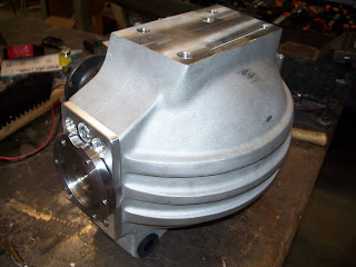
Since deciding on the Ford 9” we went ahead and ordered a rebuilt 9” Trac-Loc limited-slip differential assembly with 7.3:1 gears. We also ordered an independent rear suspension carrier made by Dutchman Motorsports. Since the IRS carrier came with Porsche 930 CV stub axles we went ahead and ordered matching CV joints for our half shafts. Below you can see the assembly, carrier and stub axles assembled.

As I mentioned before, the elEVen is going to have direct-drive system with no gearing between the motor and differential. The coupling will be done using a u-joint and a rubber flex-plate. The u-joint will allow us more freedom when mounting the motor, while the flex-plate will dampen out oscillations caused by any misalignments in the drive train.
The u-joint will be assembled out of a u-joint style slip yoke that will slide over our motor spline shaft and a custom adapter yoke, which I will be machining next week. The adapter yoke will have a 1310 size u-joint yoke on one side and a flat flange that connects to the flex-plate on opposite side. On the other side of the flex-plate will be another custom coupler with two flanges, one to connect to the flex-plate and one to bolt to the differential pinion. This coupler will also have to be machined by hand next week. Today we placed the order for the 4140 steel round stock for the pars so hopefully I will be able to get into the machine shop Tuesday or Wednesday to start making them. So far I have made some rought solid models of both couplers, which I will be refining as I discuss my plans with shop guys. Below on the left you can see the model of the adapter yoke and on the right the differential coupler.


No comments:
Post a Comment